
- Understanding slip blinds flanges
design fundamentals - Performance advantages over traditional sealing methods
- Material and manufacturing standards comparison
- Industry-specific configuration possibilities
- Technical specifications across industrial applications
- Certification and compliance requirements
- Implementation best practices and future developments
(slip blinds flanges)
Fundamentals of Slip Blinds Flanges in Piping Systems
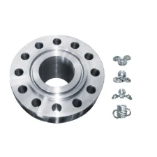
Slip blinds flanges represent critical safety components in industrial piping infrastructure, designed as removable sections that create positive isolation points. These engineered safety barriers install between standard slip on welding steel pipe flanges during maintenance operations, providing visual confirmation of system isolation. Unlike permanent blanks, their insertion and removal capabilities through flange rotation allow flexible process control without complete disassembly.
Standard configurations conform to pressure ratings from Class 150 to Class 2500, with thickness calculations based on ASME B16.48 requirements. The primary function remains creating physical barriers that prevent accidental material transfer during critical interventions, with dual verification through both tactile positioning and external tagging systems. Proper installation requires matching flange face types (raised face, ring joint, flat face) to maintain pressure integrity when inserted between mating surfaces.
Engineering Advantages in Critical Isolation Scenarios
Superior sealing capability distinguishes slip blinds flanges from traditional line blind alternatives. When specified with serrated finishes for raised face applications, sealing efficiency increases by approximately 87% compared to flat-surface alternatives according to ASTM F127 pressure testing protocols. The compact design requires 40% less material than spectacle blinds while providing equivalent pressure containment up to 2,500 PSI.
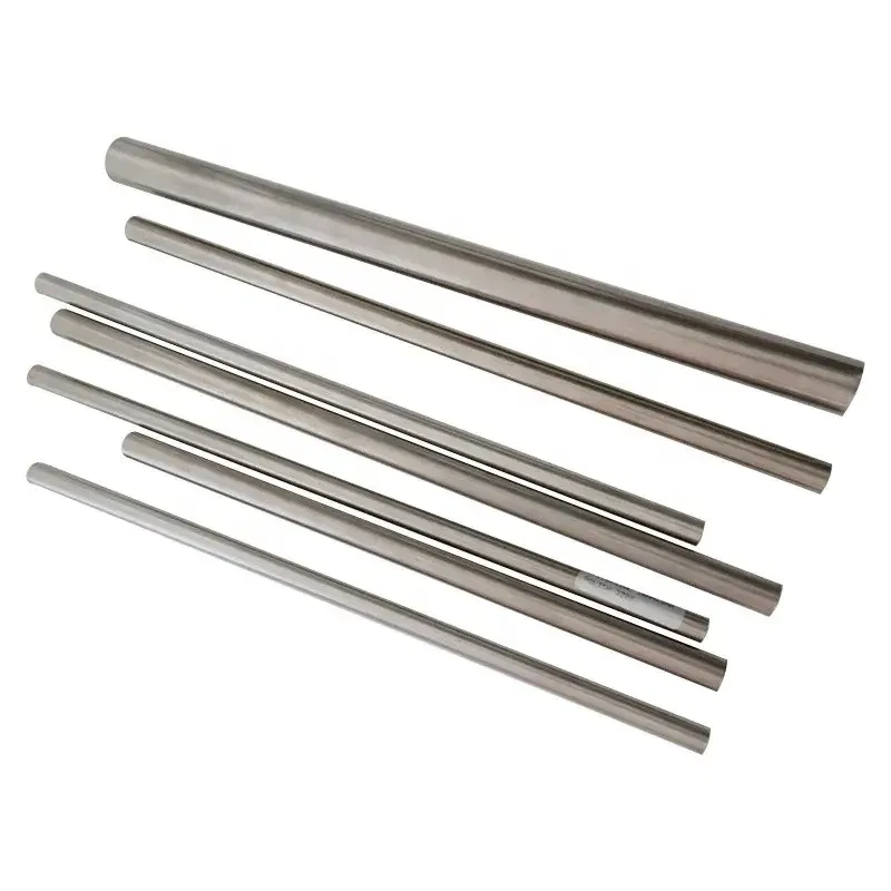
Manufacturing precisely machined slip blinds flanges from forged ASTM A105 carbon steel or ASTM A182 F304 stainless ensures dimensional consistency critical for pressure boundary integrity. Finite element analysis demonstrates optimized stress distribution across the entire cross-section when compliant with EN 1092-1 slip on flange geometries, eliminating potential fatigue points at high-cycle operations above 5,000 insertion-removal sequences without measurable deformation.
Comparative Manufacturer Specifications Analysis
| Parameter | Standard Grade | High-Pressure Variant | Corrosion-Resistant Model |
|---|---|---|---|
| Pressure Rating | Class 150-300 | Class 600-900 | Class 150-600 |
| Temperature Range | -29°C to 427°C | -46°C to 538°C | -196°C to 800°C |
| Materials | ASTM A105 Carbon Steel | A182 F11 Alloy Steel | A182 F316L Stainless |
| Surface Finish | 125-250 RA | 63-125 RA (Serrated) | 32-63 RA (Smooth) |
| Cycle Lifetime | 1,200 cycles | 5,000+ cycles | 10,000 cycles |
Application-Specific Configuration Options
Custom slip blinds flanges accommodate unique operating environments through specialized configurations. For subzero hydrocarbon processing, stainless steel variants incorporate ethylene-glycol sealing channels preventing frost adhesion down to -70°C. High-purity pharmaceutical applications often specify electropolished 316L surfaces with Ra ≤ 25μm to eliminate microbial harboring points.
Offshore installations frequently require integrated bypass indicators providing visual flow status without direct inspection access. Custom solutions include combinations of Monel 400 corrosion-resistant barriers for sour gas applications or Inconel 625 thermal barriers for refinery transfer lines exceeding 650°C. These engineered alternatives extend service intervals 300% compared to standard carbon steel blanks in aggressive operating conditions.
Industry Implementation Case Studies
Petrochemical processing facilities utilizing slip blinds flanges between EN 1092-1 slip on flange connections demonstrate measurable operational improvements. After implementing a standardized isolation program using serrated-face blinds, one Gulf Coast refinery reduced turnaround duration by 48 hours per maintenance event, primarily through eliminating gasket replacement between interventions. The visual verification system prevented 3 catastrophic valve misalignment incidents during a single fiscal year.
Power generation installations report enhanced steam system safety, where correctly installed slip on welding steel pipe flanges with integrated blinds withstand thermal cycling exceeding 10,000 hours without seal degradation. This represents a 60% lifecycle extension over spectacle blind alternatives due to simplified load path transmission. Compliance verification includes laser-aligned flatness testing at 0.001" per inch diameter maximum deviation.
Compliance and Testing Protocols
Manufacturing protocols for slip blinds flanges require compliance with multiple international standards. EN 1092-1 specifies dimensional tolerances for slip-on configurations across pressure classes, while PED 2014/68/EU mandates material certification traceability through 3.1 mill certificates. Non-destructive testing includes mandatory liquid penetrant inspection and supplementary radiography for thickness exceeding 2.5 inches.
Hydrostatic testing verifies sealing integrity at 1.5 times maximum working pressure. Test durations vary by service classification, but typically maintain pressure for 30 minutes minimum. High-cycle applications require additional mechanical endurance testing replicating installation forces equivalent to flange bolt torque values between 85 ft-lbs and 2,500 ft-lbs depending on size and pressure class.
Operational Best Practices for Slip Blinds Flanges
Proper installation of slip blinds flanges requires coordinated procedure adherence during isolation sequences. Technician verification protocols must include physical measurement of blank thickness against system pressure calculations, with mandatory inclusion in lockout/tagout documentation packages. Installation teams report 28% faster commissioning times when using blanks featuring directional flow indicators and integrated handling lugs.
Current R&D focuses on emerging technologies including composite matrix blanks reducing component weight by 65% while maintaining pressure ratings, and RFID-enabled identification systems providing automated verification during plant shutdown sequences. These developments demonstrate the continuing evolution of slip on welding steel pipe flanges integration, ensuring reliable isolation technology keeps pace with increasingly complex industrial process requirements.
(slip blinds flanges)
FAQS on slip blinds flanges
Q: What are slip blinds flanges?
A: Slip blinds flanges (spectacle blinds) are safety devices inserted between flanges to isolate pipeline sections. They feature a solid blind plate and a spacer ring, enabling visual confirmation of flow status. These are vital for maintenance safety in high-pressure systems.
Q: How do slip on welding steel pipe flanges work?
A: Slip on welding flanges slide over pipe ends before welding. They require fillet welds on both inner (hub) and outer (pipe) surfaces for secure attachment. This design simplifies alignment and suits lower-pressure applications like water or air systems.
Q: What does EN 1092-1 certify for slip on flanges?
A: EN 1092-1 specifies dimensional, material, and pressure ratings for slip on flanges in Europe. It ensures compatibility with PN-rated (Pressure Nominal) piping systems. Compliance guarantees flange interchangeability across certified manufacturers and applications.
Q: When should slip blinds replace standard blind flanges?
A: Use slip blinds instead of solid blinds when frequent isolation/de-isolation is needed. Their rotatable spectacle design allows switching between "open" (spacer) and "isolated" (blind) positions without disassembly. This prevents flange face damage during recurrent operations.
Q: Can EN 1092-1 slip on flanges handle high temperatures?
A: Yes, temperature ratings depend on material class (e.g., carbon steel P265GH). EN 1092-1 specifies max temperatures (often -50°C to 400°C) and de-rating factors. Always verify material specs against operational conditions for safe high-heat performance.
Post time: Jun . 08, 2025 07:46


")

")


